To dispose of spam email, I automatically destroy any
messages addressed to webmaster or postmaster. If you need to contact
me use  |
Last change to this document 10/03/2008
This document describes the development of an electronic inclinometer ("clino"), a surveying device designed to be used in the instrumentally hostile environment of cave exploration. There should be enough information to enable an electronics hobbyist to build a unit.
Back in about the year 2000, integrated circuit accelerometers, magnetometers
and laser pointers had become available, and were affordable for the amateur
experimenter. I conceived of the idea of building a solid state surveying tool,
the InCompass, having a built in compass, an inclinometer and a laser pointer
for sighting on the target survey station. Using an accelerometer gives not
only the tilt angle to the next survey station, but knowing the tilt angle,
the compass can be "electronically gimballed" to give an accurate
reading when tilted, unlike a conventional compass which must be held level.
The InCompass project is still not finished but work continues.
This article isn’t about the InCompass project, but about a spin off that the surveyors at South Wales Caving Club (SWCC) have found very useful: the electronic clinometer.
Dave Edwards and I worked together at this time at a London University, and I talked him into joining me on the compass project. Neither of us had any experience with microcontrollers at this stage. Initially we concentrated on just getting the accelerometer to be a sensor attached to a PIC microcontroller (PIC16F84), with an LCD display to show the output. We used a lookup table stored in some non-volatile external memory, to give us an output in degrees. This was in essence our first electronic clinometer.
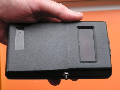
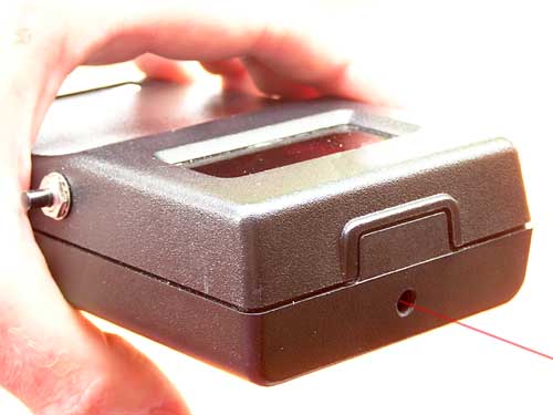
Working independently, Dave then changed the display for an LED display, and boxed the instrument in a Perspex case to make it as rugged as possible. He offered this to the SWCC surveyors for trial, and never got it back! They found it both easier to use than a traditional clino, and more accurate, and have used it ever since.
 |
Dave’s Clino Click on the pictures for a larger view |
 |
Just before Christmas 2006, an approach was made by someone who had heard that SWCC had an electronic clino, and wanted to build one for himself. Unfortunately the one we had was really a prototype, and the documentation we had was mostly in our heads, and fading with time. So at that time we couldnt really help him. Subsequently two other people at SWCC also expressed an interest. This gave me a kick start to get back into the project, which I hadnt touched for a while.
The first new units built were basically tidied up versions of Daves unit. A fresh PCB was laid out and three boards were made commercially. These boards worked out at about 17 GBP each . Of the three units, the two for our club surveyors worked well, but the third unit built for my further experimentation was unstable and inaccurate. After a lot of head scratching, it turned out that the accelerometers (Analog Devices ADXL202) had quite variable characteristics, unit to unit, and my unit had little change of T2 (see below) with temperature.
Dave had developed a clever method of using changes in the ADXL202 output pulsewidth (T2) ( see http://www.ietodd.co.uk/clino2/ADXLtemperature.pdf )(34KB) to detect the current temperature and used a lookup table to apply corrections. By chance the third unit had little change of T2 with temperature, and so the corrections were very coarse.
This third board was then modified. The original PIC16F84 was swapped, for
a newer, pin compatible microcontroller, the PIC16F87.
This has much more internal memory, so that the look up table didnt require
the external memory anymore. At the same time the resolution of the lookup table
was improved to one tenth of a degree.
The 16F87 had an internal module which could more accurately measure the duration
of the accelerometer output pulses (capture and compare module).
The resistor which determines the accelerometer total output period (T2) was
replaced with a couple of components that made the unit much more sensitive
to temperature changes. This improved the accuracy of the calibration corrections
and the original instability in readings disappeared.
At this point the design was considered to be fully working.
(I subsequently upgraded all three units to use the PIC16F88, which while functionally like the PIC16F87, has an A/D (Analogue to Digital) convertor as well, which meant we could measure the supply battery voltage).
Out of interest I decided then to do a complete redesign around the PIC16F876
microcontroller which, like the PICF87 and 88, has more internal memory than
the PIC16F84.
It also has more control lines available than the PIC16F87/88, which made it
possible to dispense with the LED driver integrated circuit, and drive the four
digit display directly from the PIC. As well as the Capture and Compare module
this PIC has an A to D (Analogue to Digital) module. This is used to continuously
monitor the battery supply, warn when it is getting low, and prevent further
use once the voltage has dropped to the point at which the voltage regulator
can no longer supply a steady voltage to the accelerometer. Circuitry was added
to isolate the battery from the whole circuit except during a measurement. The
PIC turns the power off when a reading is finished. This should extend battery
life considerably.
Considerable changes were also made to the software, putting functions like
keyboard debouncing, capture and compare, the A to D, and display multiplexing
into the interrupt routine.
The original clino had to have a set of calibration values programmed into the
external memory during manufacture. This was less than ideal. The new version
has the calibration routines built in, and can be calibrated at each of two
different temperatures by the end user. These values are stored in the PIC,
and calibration values are then automatically calculated for other temperatures
while the unit is in use.
The file ADXLtemperature.pdf (34k) describes the temperature calibration method in more detail
This final version of the clino is referred to as Version 2.0
As far as possible all the component parts were sourced from retail outlets so that anyone else should be able to acquire them easily. Farnell (http://uk.farnell.com ) are a good source of parts and will accept an order over the internet paid by credit card (minimum order value 20 GBP +vat).
The cost of parts is about 95 GBP plus board manufacture, but you could save 12 GBP if you do without the red filter for the LED display, and don't have to buy the mounting screws.
The circuit board is designed to accommodate the 14 lead Cerpak ADXL202, but
Analog Devices no longer produce it in this package, though it is still available
from Farnell.
The new ADXL202 is packaged in an 8 pin ceramic leadless chip carrier (LCC). . You can order it directly from Analog Devices with a credit card from on their website. http://www.analog.com/commerce/index.html , but they demand a VAT registration number. This means you have to order through a friendly VAT registered company. Prices are much cheaper like this, but I'm uncertain what taxes you may be liable for.
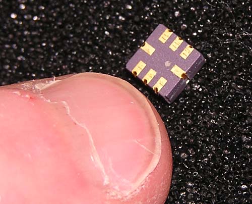
The tiny LCC package (click for a larger view)
WARNING: THE ADXL202 IS NO LONGER AVAILABLE FROM FARNELL
IN EITHER PACKAGE (17/11/2007)
The ADXL213 will also work in this project without changing any other components.
It is mounted in an LCC case (see below) and is available from RSonline http://rswww.com
for 21GBP +vat. If you want to buy more than one it's cheaper to use Digikey
UK ( http://dkc1.digikey.com/uk/digihome.html
) who charge 7.80 GBP each but with a supplement of 17GBP per order. Vat is
on top of this.
An alternative PCB layout is provided for the LCC version of the accelerometer (see at bottom of this webpage). I believe it to be correct, but it has never been built.
The PIC processor will need to be programmed, which requires some simple hardware, but unless you really want to get involved, its easier for me to do it for you. Just send the PIC to me, with stamp and addressed packaging for the return. This offer applies to cavers only.
For anyone interested I enclose the assembler file of the program, the generated
hex file and some necessary include files.
You are free to do as you wish with the software and circuit, but you may NOT use it for commercial gain without first obtaining my permission.
Microchip, the manufacturer of the PIC, supply an assembler/development environment which is free of charge and is very useful if you wish to further develop the assembler code. Look for MPLAB-IDE at http://www.microchip.com
The clino is contained in a plastic instrument case with battery compartment,
and all components are mounted on a single sided Printed Circuit Board. It is
quite possible to make this board yourself, and I include the 1x scale artwork
( http://www.ietodd.co.uk/clino2/artwork.pdf ) (984KB)
for those who wish to make their own. (The layouts can be magnified onscreen
to show more detail). It can be printed out with an inkjet onto transparent
overhead projection film, and this used to make a "contact print"
onto some emulsion coated PCB board.
(Please check when you print out the artwork that it is exactly 100mm
x 60mm as some printers may introduce their own scaling. Also, ensure
scaling is set to none in the acrobat print menu).
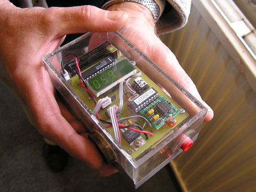
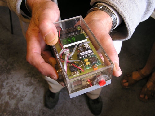
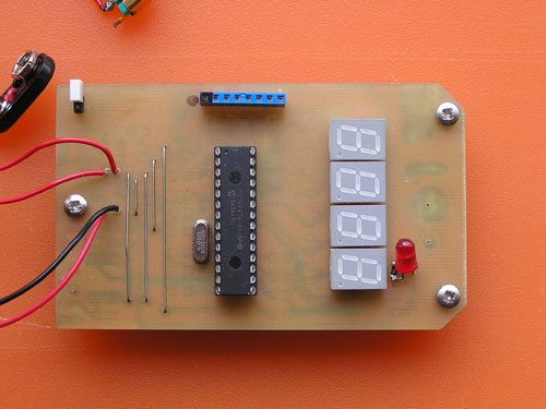
A couple of pictures of a home built board, etched and drilled by Frank, and populated by me
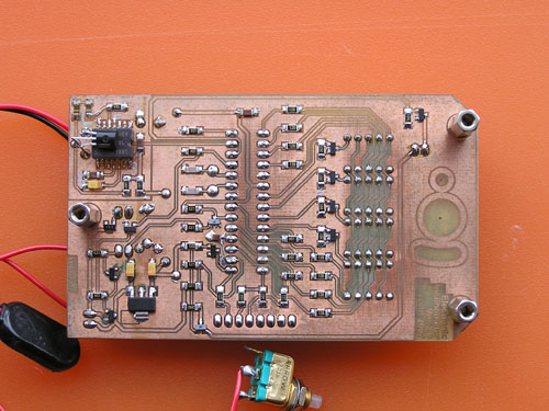 |
Click on the pictures for larger views of a homemade prototype board. |
 |
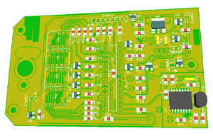 |
Here is a link to a 3D computer simulation of the bottom side of the board showing the component numbering and positions |
The mounting holes for the laser will need filing out on a home made board
to enable alignment of the mounting block, but would be routed out during commercial
manufacture. If you would prefer a professionally manufactured board, a company
called PCB-POOL make a very good job at a reasonable price.
http://www.pcb-pool.com/uk_index.htm
I paid about 17 GBP per single sided board with solder mask and routing for
three off, although one off you should expect to pay more. You can send them
a copy of my layout file http://www.ietodd.co.uk/clino2/clino876.zip
(43KB) directly to their website. The file has been zipped to prevent Windows
incorrectly identifying the file type. In the zip file you will find clino876.pcb
which is the file to send.
You can enter all the necessary information into their web form. You will need
to tell them it is an Easy-PC file, that you want a solder mask and that you
want it routed. Specify postal delivery, not courier to save money.
Many of the components are surface mount, but can be quite easily soldered by hand, providing you are experienced in soldering and are using a fine tipped iron (and, in my case, a magnifying glass).
The LM335 is mounted on the copper side of the board and its body is bent over to rest on the the ADXL202 so they should remain at the same temperature. (Apply a little thermally conductive paste if you have some).
The PIC should be mounted in a DIL socket, so it can be removed if necessary
for re-programming if a change of program becomes necessary.
(For those of you who know more about PICs, the PIC can be programmed in situ
using "In Circuit Serial Programming" (ICSP); a connector is provided)
There is a picture of the component placing at http://www.ietodd.co.uk/clino2/components.pdf
(689KB)
The circuit diagram is stored as http://www.ietodd.co.uk/clino2/schematic.pdf
(753KB)
and the list of parts, with Farnell order codes and prices, as http://www.ietodd.co.uk/clino2/parts.xls
(21KB)
Some components like the resistors and some of the chip capacitors are common
1206 sized parts, which I had in stock, so their order codes are not included.
I would advise powering the completed board by fitting the jumper link, before installing the ADXL202 and the PIC, and checking that the power and ground supplies are all as required, without any short circuits.
Manufacture of the mounting block for the laser is a bit of a problem as it needs someone with machining facilities to make a neat job. I include a drawing of the block I used http://www.ietodd.co.uk/clino2/block.pdf (269KB). This hangs beneath the PCB, and the laser is held in place by the grub screw. The type of cheap laser used here has a beam that may come out at quite an angle relative to the body of the laser. So the idea is to rotate the laser in the mounting block until the off axis beam is as near horizontal as possible, and then tighten the grub screw. Then swing the block left or right on its mountings until the beam is straight ahead. Minor errors in getting the beam horizontal can be corrected in software (see calibration instructions).
Probably the most accurate way to set the beam level, is to use a water level. This is just a length of transparent hosepipe, the longer the better, filled with water. One end is held near the laser exit port and the water level adjusted to be level with the laser beam. The angle of the laser beam is then adjusted until it is also level with the water in the distant end of the hose. The laser beam is then exactly horizontal.
The trigger switch is the other mechanical problem. The unit only has the one switch for both turning the unit on, and for use as a trigger to take a measurement. To avoid disturbing the clino as the trigger is pushed, the trigger should only need a very gentle push. The switch should not be mounted on the top of the unit, as pushing the button will tend to lower the beam slightly. Maybe the switch should be very sensitive but have some mechanical protection to avoid turning the unit and the laser on accidentally during transport. This might also help prevent the ingress of water and cave dirt. I dont have a good solution to this problem so far, so please let me know if you think of something ingenious.
see schematic.pdf (753KB) for the circuit diagram.
The battery supply to the circuit is via a protection diode to a P channel CMOS
switch (Q8). When this switch is off (its normal state), the current flowing
from the battery is only about a microamp. When the trigger button on the unit
(CONN2) is pushed, the PMOS switch turns on, and the 78L05 voltage regulator
supplies the PIC with current, which starts it executing its program. The PIC
then holds the PMOS switch on by applying volts to the gate of Q6. After a measurement
is made the PIC turns off the PMOS switch, effectively isolating the circuit
from the battery again. In use this should extend battery life considerably.
The jumper link CONN4, when fitted, supplies the circuit continuously with
power. This is used for programming and to put the clino into calibration mode.
When the circuit is powered the switch at CONN2 is used as a trigger by pulling a port line on the PIC low via Q5. R24 and R27 form a potential divider which supplies half the unregulated battery voltage to the A to D converter in the PIC. Using the regulated supply as a reference the PIC triggers a warning when the battery volts are getting low. C9 is fitted to reduce high frequency noise reaching the A-D.
Q9 is wired as an emitter follower. Its base is connected to regulated 5 volts which fixes the emitter at about 0.6 of a volt less. This is used to feed the laser. The laser supply current is thus taken from the non-regulated supply.
Q1, an NMOS switch grounds the other side of the laser, turning it on, when the PIC sets its gate high.
The ADXL202 accelerometer is fed with regulated 5 volts via R14, which with C2, helps reduce any high frequency noise generated by the PIC. Only the X channel is used. The terminal voltage of the LM335 is strictly proportional to the absolute temperature. This causes the current flowing from the T2 pin, and thus the frequency of the output waveform, to change markedly with temperature. Measuring the T2 period is thus a good indicator of temperature for applying temperature corrections. The high value of C5 reduces noise in the output signal, but at the expense of slowing down response time.
The X channel output of the accelerometer is fed to the Capture and Compare pin of the PIC where the duty cycle is accurately measured. This data, averaged over 64 cycles, to reduce noise, is then used to calculate the tilt angle of the accelerometer (acceleration due to gravity).
Each segment of the 7 segment LED display is connected in parallel with the other 7 segment displays, and connected to an output port line from the PIC. Which display is actually lit at any time is determined by whether its cathode is grounded by the PIC via Q2, Q3, Q4 and Q7. The PIC illuminates the individual digits in quick succession (multiplexing) so the whole display appears to be on continuously to the human eye.
The connections —MCLR, PGC, PGD and GND on CONN3 are provided to enable the PIC to be programmed in situ ( ICSP ).
The accelerometer chip in the Clino (ADXL202) is sensitive to temperature, and so must be calibrated to give accurate results. This involves taking a pair of measurements at a high temperature, and a pair at a lower temperature. (in the airing cupboard and in the fridge maybe). The actual temperature does not need to be known, but the unit should be given plenty of time to temperature stabilize.
Operating the unit at temperatures below that at which
the cold calibration was performed, showed up a bug in the software, however
the behaviour was correct at temperatures above the cold calibration temperature.
I have now fixed the problem (10/3/2008).
For the first measurement, at each temperature, the unit is pointed vertically up. This subjects it to a -1g acceleration (gravity). For the second measurement it is pointed vertically down and experiences a +1g acceleration. The difference between the obtained readings is therefore caused by a known 2g change in acceleration. These values are then stored in the Clino and used to calculate the correct calibration values for any other temperature (this could be outside the two calibration temperatures).
Before a calibration can be performed, a jumper is used to short out the 2 pin connector on the bottom left corner of the circuit board (CONN4). This also applies power continuously to the circuit. Having fitted the jumper, put the lid back on the instrument case (just hold it with a rubber band, to save putting the screws back in). The lid will keep the internal temperature more stable during the actual calibration. Hot and cold calibrations are performed independently, and either can be done first.
Because of the difficulty of mechanically ensuring the laser and the accelerometer are exactly coplanar, the menu option "Corr" when selected will give you a choice of adding, or subtracting, a small offset from the clino reading.
When calibrations are complete, the jumper link on the circuit board should
be removed, and parked on just one pin. The unit now cannot enter calibration
accidentally.
The Clino is now ready to use and shouldnt require frequent calibrations. Periodic
checks of the unit accuracy is advised.
When in normal use, with the jumper link removed, the battery is effectively
disconnected from the circuitry, until the button is pressed.
The laser will now be turned on, and the display will show the continuously
updating angle from horizontal. When the laser beam is pointing at the target
survey station, hold the unit as steady as possible, count to 3 (to allow for
settling), and push the button gently.
The laser will turn off, and the angle when the button was pressed, will be
held on the display, which will flicker gently to indicate a held reading.
After recording the value in the log book, another press of the button will
disconnect the battery again.
In this way battery life should be maximised.
In use, the output voltage of the 9 volt battery (MN1604 , 6LR61, or as it
used to be called, a PP3) will slowly decrease.
A 5 volt regulator ensures that the voltage supply for the accelerometer remains
constant.
When the battery voltage drops to 7.5 volts, the bottom left hand segment of
the display will flash. The unit is still useable, but this is a warning that
the battery will soon run out.
When the battery voltage drops to about 7 volts, it is close to the point at
which the regulator can no longer keep a steady 5 volt output. This is sensed
by the PIC, and the display will read "FLAt". The unit cannot then be used until
a replacement battery is fitted.
The following files are available for download from this website
All files except P16F876.inc and clinotemp.pdf are Copyright Ian Todd 2007.
They may be freely used for non-commercial purposes
Easy-PC pcb file clino876.zip (43KB)
The file has been zipped to prevent Windows incorrectly identifying the file
type. In the zip file you will find clino876.pcb
Circuit diagram schematic.pdf (753KB)
1:1 artwork artwork.pdf (984KB)
Component placing on PCB components.pdf (689KB)
Parts List parts.xls (21KB)
Easy-PC pcb file LCCclino876.zip (44KB)
The file has been zipped to prevent Windows incorrectly identifying the
file type. In the zip file you will find LCCclino876.pcb
1:1 artwork LCCcopper.pdf (984KB)
Main assembler file clino876.asm (69KB)
Assembled Hex file (the file that is actually loaded into the PIC) Clino876.HEX (18KB)
Include files (all small files)
arcsin10.inc
ccp1.inc
P16F876.inc
options.inc
seg876.inc
intcon.inc
My thanks go to my friends who have helped me with this project, particularly
Trevor Woolvin who helped both with the circuit design and software, and built
my first PIC programmer. Also Frank Vine for the use of his amazing homemade CNC PCB
drilling machine.